Key Components of a Clutch System: A Technical Breakdown

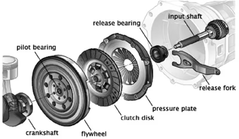
In the world of mechanical engineering and automotive technology, the clutch system is a crucial component that ensures smooth power transmission from the engine to the drivetrain. The clutch’s primary role is to engage and disengage the power flow, allowing for smooth gear shifts and vehicle control. In this blog, we will delve into the various parts of a clutch, illustrated by the diagram provided, and discuss their functions and technical importance.
How Windshield Wipers Work and Why They Matter
1. Flywheel
The flywheel is a large, heavy disc that is mounted on the engine’s crankshaft. It provides inertia to keep the engine rotating smoothly between power strokes and engages the clutch disc to transmit torque. The flywheel plays a pivotal role in stabilizing the rotational energy and helps in smooth acceleration and deceleration of the vehicle.
2. Clutch Disc (Friction Disc)

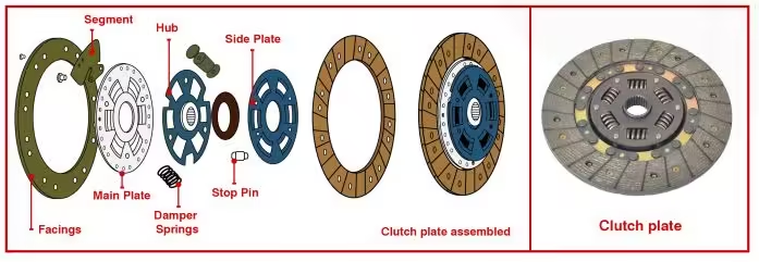
The clutch disc, sandwiched between the flywheel and the pressure plate, is the key to transferring torque from the engine to the transmission. It has friction facings that contact the flywheel and pressure plate. When the clutch system is engaged, these friction surfaces press against the flywheel, creating the necessary friction to transfer power.
- Friction Facings: These are designed to endure high levels of heat and wear due to the constant friction during engagement and disengagement.
- Center Hub (Splined): This is the part that connects to the transmission input shaft via splines, allowing the disc to move axially but rotate with the input shaft.
3. Pilot Bearing
The pilot bearing, located at the end of the crankshaft, supports the transmission input shaft. It ensures smooth operation of the clutch system by reducing friction between the spinning components, especially during the engagement and disengagement process.
4. Pressure Plate Assembly

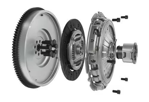
The pressure plate assembly, composed of the pressure plate, diaphragm spring, and fulcrum ring, is responsible for applying pressure to the clutch disc. The pressure ensures that the clutch disc remains in firm contact with the flywheel when engaged, effectively transmitting torque.
- Pressure Plate: This heavy-duty plate presses the clutch disc against the flywheel to transfer power.
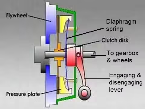
- Diaphragm Spring: A spring-loaded mechanism that provides the clamping force required to engage the clutch. When the clutch pedal is depressed, the diaphragm spring releases the pressure, allowing the clutch disc to disengage from the flywheel.
- Fulcrum Ring: This ring serves as a pivot point for the diaphragm spring, ensuring balanced and smooth movement during clutch engagement and disengagement.
5. Clutch Fork and Thrust Bearing
The clutch fork, controlled by the clutch pedal, plays a direct role in engaging and disengaging the clutch. When the clutch pedal is pressed, the clutch fork pushes against the thrust bearing (also called the release bearing), which in turn presses on the diaphragm spring. This movement reduces the pressure on the clutch disc, allowing it to disengage from the flywheel.
- Thrust Bearing: This bearing ensures smooth operation by allowing axial movement of the diaphragm spring when the clutch is actuated.
6. Transmission Input Shaft and Splines
The transmission input shaft is connected to the clutch disc and transmits engine torque to the gearbox. The splined design allows the clutch disc to slide along the shaft while rotating with it, facilitating smooth engagement and disengagement of gears.
7. Clutch Pedal
The clutch pedal is the user interface of the clutch system. When the driver presses the clutch pedal, it transmits mechanical or hydraulic force to the clutch fork, which then operates the pressure plate assembly to engage or disengage the clutch.
Functionality in Detail

The clutch system operates in two fundamental states: engaged and disengaged.
- Engaged Clutch: When the clutch pedal is released, the pressure plate presses the clutch disc against the flywheel. This engagement transfers engine power to the transmission input shaft, which ultimately drives the wheels.
- Disengaged Clutch: When the clutch pedal is pressed, the pressure plate retracts due to the movement of the diaphragm spring, allowing the clutch disc to separate from the flywheel. This disengages the engine from the transmission, allowing the driver to change gears without interrupting power flow to the wheels.
Clutch Definition: Learn its Working, Types, Applications, Advantages and Disadvantages
Conclusion
A clutch system may appear simple on the surface, but its components work together in harmony to provide seamless power transmission and vehicle control. Understanding these parts—from the flywheel to the clutch fork and thrust bearing—helps in diagnosing mechanical issues and optimizing performance. Whether you are a mechanic, engineer, or car enthusiast, a deeper knowledge of clutch mechanics is essential for mastering the art of vehicle dynamics.
Do you have questions about how these components work in specific automotive systems? Drop a comment below, and let’s discuss!
